Tire Digital Twin – Abstract
A tire digital twin is an extremely integrated and multi-physical system. From only a mechanical point of view, tires are representedby highly composite multi-layered structures, consisting of a multitude of different materials, synthesized in peculiar rub-ber matrices, to optimize both the performance and the life cycle. During the tire motion, due to the multi-materialthermodynamic interaction within the viscoelastic tire rubber matrix, the dynamic characteristics of a tire may alter con-siderably. In the following paper, the multibody research comfort and handling tire model is presented.
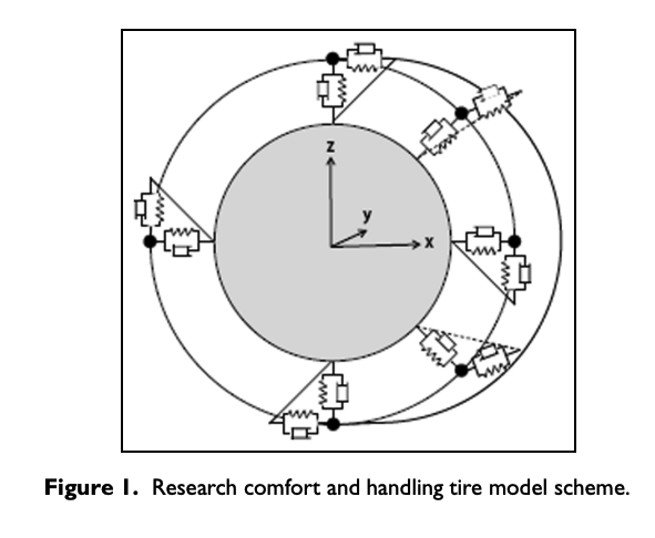
The main purposeof the research comfort and handling tire is to constitute a completely physical carcass infrastructure to correctly trans-mit the generalized forces and torques from the wheel spindle to the contact patch. The physical model structure is rep-resented by a three-dimensional array of interconnected nodes by means of tension and rotational stiffness and damperelements, attached to the rim modeled as a rigid body. Research comfort and handling tire model purpose is to consti-tute a structural physical infrastructure for the co-implementation of additional physical modules taking into account themodification of the tire structural properties with temperature, tread viscoelastic compound characteristics, and weardegradation.
At the stage, the research comfort and handling tire discrete model has been validated through both staticand dynamic shaker test procedures. Static test procedure adopts contact sensitive films for the contact patch estima-tion at different load and internal pressure conditions, meanwhile the specifically developed sel test regards the tiredynamic characterization purpose at the current stage. The validation of the tire normal interaction in both static anddynamic conditions provided constitutes a necessary development step to the integration of the tangential brush interac-tion model for studying the handling dynamics and to the analysis of the model response on the uneven surfaces.
Introduction – TIRE DIGITAL TWIN
The tire dynamic behavior has to be considered from an early design stage as stability, comfort, handling, and noise, vibration, and harshness (NVH) performances depend on it.1–3 On the other side, the characterization of the tire behavior is one of the toughest things because to provide a complete and precise insight on the tire entire working range, the tire should be tested with the measurement accuracy obtainable only in laboratory-controlled conditions and on the vehicle moving on the real road surface by means of an expensive instrumentation.2,4
Furthermore, the tire behavior deeply depends on the compound and carcass structural characteristics,5 whose properties in their turn are linked to and change with the tire temperature and the air pressure inside the wheel chamber, without mentioning the influence on above parameters of the vehicle dynamics itself, as the sliding speed of the compound upon road granularity varying the excitation frequency of the stress distribution within the rubber viscoelastic material.6,7
It is worth to highlight that the majority of the test rigs analyze the tires on smooth surfaces and in steady-state conditions. Therefore, a modeling approach becomes even more vital when the tire must be studied in transient conditions on pavements with asphalt roughness and on uneven roads.8,9
There are two main approach branches commonly adopted regarding the tire modeling: empirical and physical.10–12
The first approach, very popular because of its intrinsic simplicity and the low computational cost, particularly suitable for the real-time applications, avoids the tire physical modeling and determines the interaction forces on the basis of empirical models, as “Magic Formula.”11,13,14 In this case, the greatest challenge engineers tackle adopting the empirical models concern the tedious identification process of a suitable coefficient parameters set on the basis of tests to be carried out for each tire in analysis.15,16
The second approach involves physical system modeling, with its geometrical and physical characteristics, resulting in obviously more onerous from the computational point of view, but it also allows a deeper understanding of the complex phenomena related to the tire behavior in its interaction with vehicle and road.17,18
Several papers found in the literature refer to the tire modeling using the finite element method (FEM),19–21 which, due to a particularly significant computational load, are adopted to evaluate static characteristics, stiffness, resonant frequencies, and vibration modes.22,23
Another approach consists in the representation of the tire by means of a certain number of nodes physically interconnected to reproduce the degrees of freedom and constraints of the real structure.24–26 According to Kim et al.27 and Oertel and Fandre,28,29 the SWIFT model,30 the FTire model,31 and the CDTire32 are among the most commonly adopted multibody models in the automotive field, useful to study dynamic phenomena as braking, cornering, and driving on uneven pavement surfaces.33
The SWIFT model is represented by means of a rigid ring model, able to describe the tire belt behavior, connected to two tire–road interaction sub-models by means of stiffness elements: an enveloping model to take into account of the road unevenness and a slip model. The SWIFT model aims to represent the tire dynamic behavior up to 100 Hz range, where the tire belt remains quasi-rigid and circular.
The Ftire structure is described by means of a three-dimensional mass points system, whose elasticity is expressed by tensional and rotational springs to represent the tire belt. The tire sidewalls are assumed massless, modeled as radial and tangential spring and damper elements, coupling the flexible belt nodes to the rigid rim, behaving as membranes pre-tensioned by the internal pressure. The tire tread is described by means of a field of elastically deformable brush elements.
The CDtire modeling approach is based on the concept that the local deformation behavior of a real tire should be identical to the deformation of a multibody tire model. Consequently, the model structure consists of a detailed shell system schematizing tire belt and sidewalls. The inertial properties of the shell nodes are represented by discrete mass points with 3 degrees of freedom per node. The elastic shell properties are reproduced by means of elastic membranes and the bending is described by an adaptation of the Kirchhoff–Love plate theory.34,35
Starting from the cited three-dimensional tire dynamic models, the research comfort and handling (RCH) tire physical model has been developed. The physical RCH-tire model structure is represented by a three-dimensional array of interconnected nodes by means of tension and rotational spring and damper elements, attached to the rim modeled as a rigid body. The simple model structure, particularly suitable to be effectively characterized by means of static and specifically developed dynamic test procedures, makes the RCH-tire a valuable solution to study and understand the tire behavior.
It is also worth to mention that the RCH-tire could definitely provide a relevant physical infrastructure to completely understand the tire behavior in dynamic transient conditions, in particular, taking into account the influence of other connected physical phenomena as thermal effect on tire stiffness and compound characteristics or wear impact.36
RCH model
A completely physical multibody structure, at the base of the RCH-tire model, becomes completely necessary when it comes to archive the goal of obtaining the interaction output in terms of velocity and pressure local distribution within the dynamic contact patch.37 Once the physical structural model has been properly characterized and validated by means of specifically designed static and dynamic tests,38,39 the aim of the RCH-tire model is to represent a physical infrastructure for interconnected physical phenomena (tread viscoelastic characteristics, thermal dynamics influence, road and wear impact influence), where the tire stiffness and compound properties can vary considerably depending on the thermal state, boundary and working conditions, and the wear degradation progress.
RCH-tire is a three-dimensional physical model of the tire carcass, consisting of mass nodes connected with a certain number of equivalent spring and damper elements to reproduce the tire structural dynamic behavior. The three-dimensional node system is interconnected by tension and rotational spring and dampers to reproduce the equivalent design viscoelastic characteristics accurately differentiated in distinct geometrical zones of a tire structure: belt, shoulders, sidewalls, and bead, as represented in Figure 1
The following simplifying assumptions have been adopted to model the carcass with the minimum set of parameters:
• Tire is considered slick and geometrically symmetrical toward the zx longitudinal plane;
• Tire belt properties are differentiated toward the tire meridian yz and parallel zx planes, with physical inertial and structural properties assumed to be identical within the same planes;
• Rim is considered rigid and cylindrically shaped, connected to the tire sidewall in a way to neglect the possibility of reciprocal sliding between the tire bead and the inner groove of the rim.
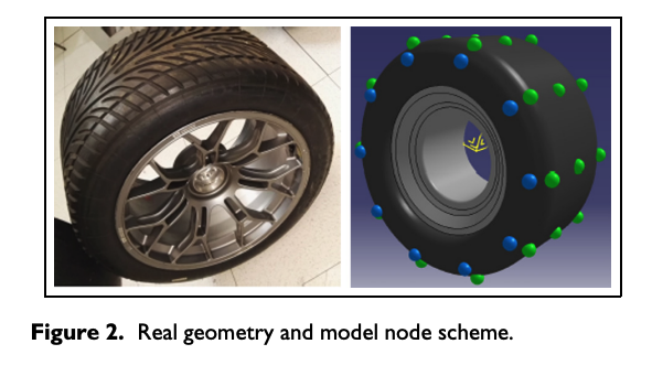
To initialize the model system node, the tire geometry has to be implemented starting from a real tire as depicted in Figure 2. Nodes of different colors (belt nodes in green and sidewall nodes in blue) are represented to highlight both distinct inertial and structural properties, taken into account during the preliminary discretization phase.
Mathematical model: kinematic and dynamics
The dynamics of the RCH-tire model is governed by Newton’s law, where the model is described by means of 3*nE*nM + 6 DoF within second-order differential non-linear equations of motion, described by the following system
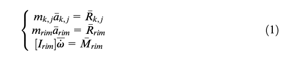
where 𝑎¯𝑘,𝑗 is the acceleration of the k,jth node; 𝑅¯𝑘,𝑗 is the resultant of the forces acting on the k,jth node; 𝑎¯rim is the acceleration of the rim center of gravity G; 𝜔·¯ is the angular acceleration of the rim; and 𝑅¯rim and 𝑀¯rim are the force and the moment resultants of forces, respectively.
The ordinary differential equation (ODE) system (1) is numerically solved in the MATLAB environment using ode45 solver (a Runge–Kutta method with variable step).
Tire nodes
Modeled according to Lorenz et al.,7 the internal forces Fstructural,k and Fstructural,b are represented as a sum of the elastic reactions of the linear springs dampers, and the elastic and damping elements representing the torsional springs, acting on each k,jth node.
Therefore, on each distinct node Pk,j, an equivalent forces set is applied, taking into account both internal structure reactions and boundary load working conditions
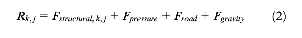
• Internal force due to linear deformation of the tire (belt and sidewall), denoted as Fstructural,k,j
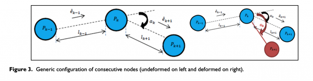
Considering the scheme in Figure 3, the forces Fstructural,elastic in equation (3) and Fstructural,viscous in equation (4), where kk,j and bk,j are, respectively, the elastic stiffness and viscous damping for a generic Pk,j node, whose properties depend on the position of the k,jth node within the tire structure system, are expressed as follows
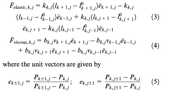
•Internal force due to equivalent bending effect within the tire structure, denoted as Fstructural,b
Considering a generic instant, where the relative position of k + 1th node has changed toward the position of kth node, the equivalent torque structural internal forces have to be described. The angle ak between the unit vector of two consecutive links is defined by means of the following cross product

In Figure 3 (on right), the deformed node configuration is represented, where Δak has modified the initial node configuration. To define the equivalent couple of forces to represent the tire membrane bending reaction structural behavior, the following unit vectors are introduced
Since the nodes are defined in R3 as mass points with three linear degrees of freedom, an equivalent bending system has to be introduced. In Figure 4, a generic variation of the angle ak,j between two consecutive unit vectors at a generic instant is represented.
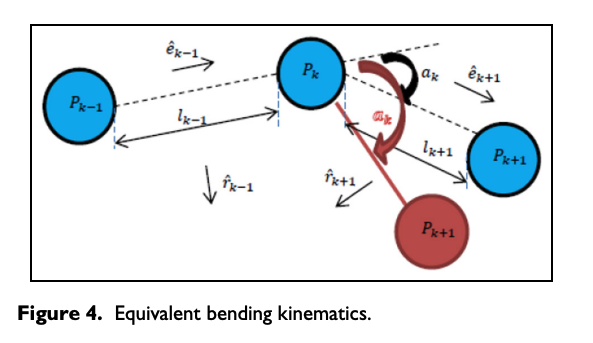
Since the modification of the initial tire configuration in terms of reciprocal node positions produces not only the reaction linear forces but also the equivalent torque forces, the latter ones dynamics is illustrated in Figure 5.
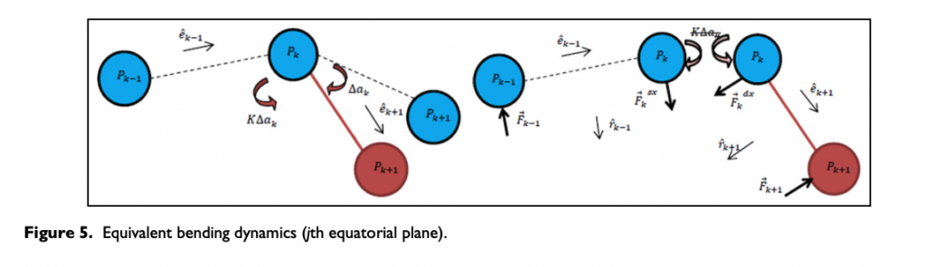
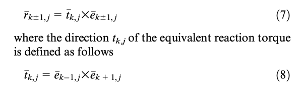
From the mathematical point of view, the equivalent torques are implemented in terms of additional linear structural reactions as follows
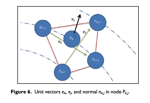
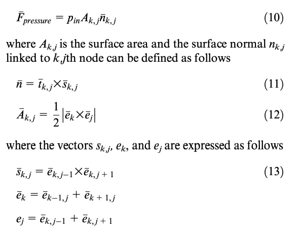
The internal force Fpressure due to the effect of pressure pin is given by
• External force due to the interaction with road pavement Froad
Since the tangential tire–road interaction has not been implemented at the current development step, the only external force due to the interaction with road is the sum of the normal reaction to the road profile.
The road normal interaction force Froad on the k,jth node is given by
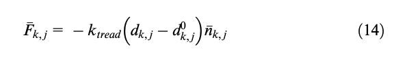
where dk,j and 𝑑𝑘,𝑗0 are, respectively, the deformed and the nominal depth of the compound in the k,jth node at a generic instant.
• Force of gravity Fgravity
The gravitational force Fgravity is obviously given by
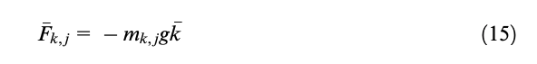
where g is the acceleration of gravity, k represents the direction of z axis in absolute reference, and mk,j is the mass of k,jth node, depending on its position within the tire structure.
Rim body
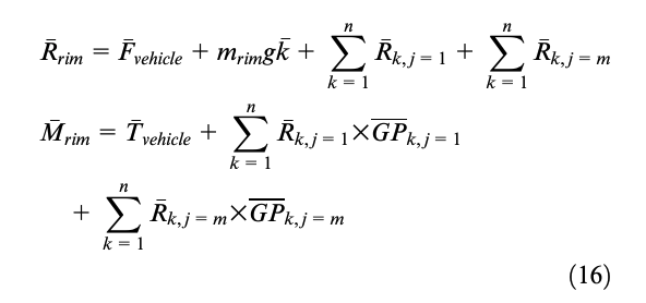
The key difference between a particle and rigid body is that a particle can undergo only translational motion, whereas a rigid body can undergo both translational and rotational motion. Therefore, supposing the rigid rim motion interested by only three kinds of forces:
• Internal structural forces exchanged with the sidewall, given by the elastic and viscous reactions of the tire system of spring and dampers;
• Forces exchanged with the vehicle, given by the resultant Fvehicle of the forces exchanged with the vehicle and by the driving/braking torque Tvehicle acting on the rim;
• Force of gravity.
The resultant and the resultant moment of the above forces are the quantities Rrim and Mrim, which can be therefore obtained by the following expressions
Testing procedure
The experimental data available are referred to a SEL tests performed on a GT tire (size 31-71-18) at an environmental temperature of 25°C, employing a non-rolling tire. It has to be highlighted that to properly characterize the tire behavior, the dynamic testing should involve longitudinal and lateral maneuvers in rolling conditions. This will be achieved in further developments, since a complete mathematical description of a tangential interaction becomes necessary to understand the model behavior for the validation of the experimental results.
Therefore, to characterize the RCH-tire model behavior, both static and dynamic characterization tests have been performed and then compared with the results of the RCH-tire model, with non-rolling tire condition.
A particular convenient testing procedure to determine the equivalent viscoelastic tire carcass properties proved to be the radial sel (strain energy loss (SEL)) test, evaluated at different values of frequency and load amplitude.
Static characterization
The tire static characterization procedure considers the pneumatic tire not rolling with different values of vertical loads applied at different internal pressure values. Typical experimental data obtained are the radial displacement of the rim center and the contact patch extension, in terms of shape and pressed area, dependence on the above parameters.
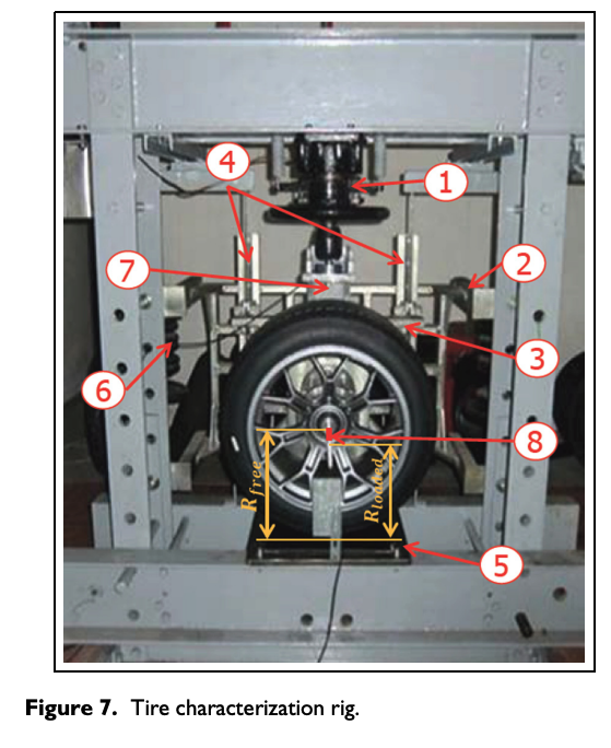
The tire static test rig for applying the vertical road is essentially composed by manually actuated hydraulic press (Figure 7(1)), a fixed frame integral with the press fixed structure (Figure 7(2)), a vertically mobile frame (Figure 7(3)) in contact with a press actuator on which a universal quick flange to lock the wheel is mounted, two linear guide rails (Figure 7(4)) placed along the vertical direction between the fixed and the mobile frame, a fixed plate (Figure 7(5)) integral with the press fixed frame, a system with manually variable weights (Figure 7(6)) to balance the weights of the mobile frame and the wheel so that the tire has no initial vertical load. The test bench is equipped with the following measurement instrumentation: a strain gauge load cell (Figure 7(7)) to measure the vertical load applied by the press and a draw-wire sensor (Figure 7(8)) to evaluate tire deformation along the vertical direction.
The typical tire static characterization output in terms of contact patch extension and shape and radial lowering in different load and internal pressure conditions for tire static characterization is provided in Table 1.
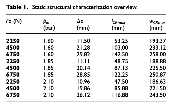
Moreover, lowering information obtained will be used to validate the RCH-tire model response in the same working conditions.
Dynamic characterization
The energy dissipated by the tire as a result of cyclic deformations is called SEL. This dissipation is due to a superposition of several phenomena: intra-plies friction, friction inside plies, non-linear viscoelastic behavior of all rubbery components.
The cyclic deformations to which the system is subject occur with a frequency corresponding to the tire rotational speed. During the rolling, in fact, portions of tire, entering continuously in the contact area, are submitted to deformations which cause energy loss and then heat dissipation. Generally, to properly characterize the viscoelastic dissipation behavior of a tire, an experimental procedure consisting in deforming the tire cyclically in three directions (radial, longitudinal, and lateral) has to be carried out.13
Radial test consists in a quasi-static tire radial compression; it is realized manually actuating the press while the horizontal movable plate is kept stopped, and it is conducted with different values of the inflation pressure. During this kind of test, the vertical load and the corresponding strain are acquired, and consequently it is possible to determine the normal interaction characteristic and the radial stiffness.
The experimental data coming out from this test are the time histories of the vertical load Fz(t) (tire normal interaction force with the flat surface) and the radial deformation of the tire δ(t).
The tests are performed at three levels of vertical load amplitude and four levels of frequency (1, 10, 20, and 30 Hz).
The typical output is a cycle (in Figure 8), represented in a force versus displacement diagram, for which the area is calculated in steady-state conditions, considered as an index of the dissipated power, converted in heat. As expected, increasing the actuator load frequency rapidly increases the energy loss (hysteresis cycles area).
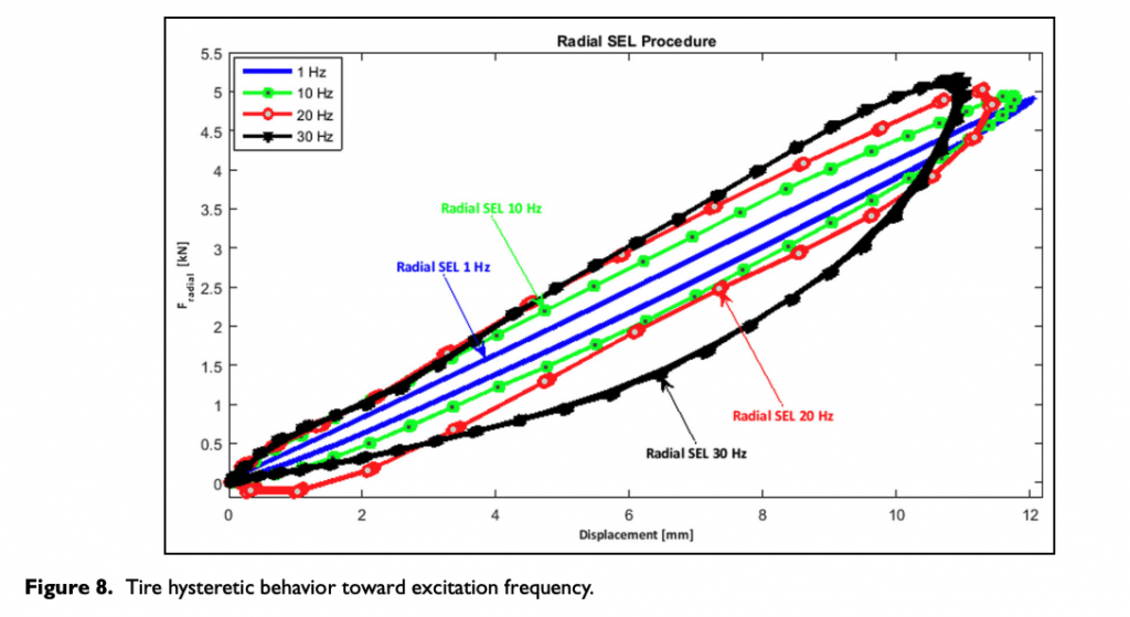
It is important to highlight that estimated energies do not exactly coincide with the ones dissipated in the actual operative conditions, as the deformation mechanism is different; it is however possible to identify a correlation between them on the basis of coefficients estimated from real data telemetry.
Interpolating all the results obtained by means of the test plan, a specific analytic function could been identified to properly feed an available tire thermal model.
Results
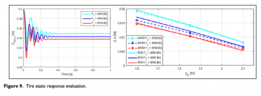
The initialization simulation phase of the model requires to calculate the positions of nodes P, as a function only of geometric shape. In simuation phase, the linear distances l0 and the relative angles a0 within the tire node system are set and the tire system is not yet in contact with road pavement (Figure 9).
The second stage consists in providing the internal pressure as a function of time. Once the RCH-tire model behavior has stabilized in the above conditions, the tire system is brought into contact with the road surface.
Static results
In Figure 9, the outputs of some simulations carried out with the described model under three different load configurations are represented. Both transient and steady-state phases are present in the static radial test.
Considering the RCH-tire model behavior only in steady-state conditions, when all the transient dynamic phenomena are ended, the static response can be compared to the acquired data.
The results of the RCH-tire model seem to be in a good agreement with the data obtained from the static characterization procedure, as represented in Figure 9. They are obtained by running some simulations in which the internal pressure of the tire is fixed at values of 1.60, 1.85, 2.10 bar and the vertical load varies for fixed steps.
Figure 10 represents a complete three-dimensional structure of the RCH-tire model, illustrating the vertical pressure distribution within the contact patch.
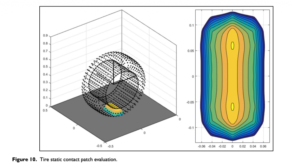
It is important to highlight that the parameters adopted in the analysis (stiffness and damping) are constant and only depend on their position within the tire three-dimensional node system (tread, shoulder, sidewall, etc.) and on the direction of the physical link (elastic and damping) describing the connection between the consecutive nodes: lateral and circumferential. The aim of the first version of the RCH-tire model was to understand whether the RCH-tire multibody approach could be appropriate to describe the large deformation of the tire structure even with completely linear elements.
Dynamic results
The simulations are performed considering three steps of imposed travel displacement δz. Each simulation is performed with a duration of 5 s, sufficient to allow the extinction of the undesirable dynamical effects on the model outputs.
The model output to sel test dynamic input in terms of imposed displacement time history is represented in Figure 11. The peculiar modification for radial sel test in terms of dissipated energy and cycle shape, output of the RCH-tire model at different excitation frequencies, seems to be in a good agreement with the experimental ones as described in Figure 8.
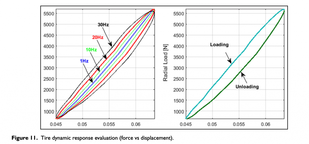
In Figure 12, the RCH-tire model results are compared to the experimental data obtained by means of a radial sel test.
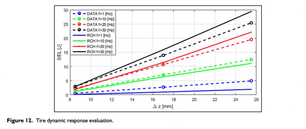
Despite the preliminarily hypothesized completely linear behavior of all the structural parameters involved, the RCH-tire model achieves a good result, reproducing good global trends, as a function both of imposed vertical load and of excitation frequency.
Further developments could introduce the non-linear structural elements behavior, function of induced strain, internal pressure, wear/degradation phenomenon, and finally working temperature, to completely reproduce the tire carcass behavior and to model the tangential interaction.
Conclusion – TIRE DIGITAL TWIN
In the present paper, RCH-tire carcass model has been presented. The RCH model structure is constituted by a three-dimensional mass node infrastructure, interconnected by discrete concentrated tension and damper elements. The node characteristics in terms of mass, stiffness, and damper characteristics have been properly differentiated depending on both the diverse zones of the tire structure the nodes belong to (belt, shoulder, sidewalls, etc.) and the direction of the load propagation the nodes are subjected to (the circumferential along the longitudinal direction and the lateral one) due to composite significantly asymmetrical properties.
Starting from the described discrete approach showing an interesting potential to reproduce large motions and structural deformations, the further intention of the authors is to couple the multibody dynamics of the physical models developed by the research group. In particular, following steps will regard the implementation of the thermal, grip, and wear models to take into account of the structural and interaction dependences on local variables, as temperature of different tire layers, tread viscoelastic properties, and wear degradation phenomena. In this way, RCH-tire model could represent a valuable instrument to obtain the information necessary to optimize the performance of tires in terms of available amount of grip in real time to understand and minimize the degradation phenomenon and the temperature thermal range on different tracks and in different ambient and track conditions.
Declaration of Conflicting Interests
The author(s) declared no potential conflicts of interest with respect to the research, authorship, and/or publication of this article.
Funding
The author(s) received no financial support for the research, authorship, and/or publication of this article.
ORCID iD
Flavio Farroni https://orcid.org/0000-0001-8257-5534
Appendix 1
Notation
𝑎¯𝑘,𝑗 acceleration of the k,jth node (m/s2)
𝑎¯rim acceleration of the rim center of gravity (m/s2)
ak,j angle between consecutive unit vectors (rad)
Ak,j surface equivalent area for the k,jth node (m2)
bk,j viscous linear damping for a generic Pk,j node (N s/m)
Fstructural,k,j resultant of internal forces acting on the k,jth node (N)
Fpressure pressure force (N)
Froad road interaction force (N)
Fgravity gravity force (N)
Fvehicle resultant of the forces exchanged with the vehicle (N)
[Irim] inertia rim matrix (kg/m2)
ktread compound elastic linear stiffness (N/m)
kk,j elastic linear stiffness for a generic Pk,j node (N/m)
mk,j equivalent mass of k,jth node (kg)
mrim mass of wheel rim (kg)
𝑀¯rim resultant moment of forces on rim (N m)
Pin internal pressure (N/m2)
Pk,j k,jth node (kth meridian and jth planes) (–)
𝑅¯𝑘,𝑗 resultant of the forces acting on the k,jth node (N)
𝑅¯rim resultant force on rim (N)
Tvehicle driving/braking torque Tvehicle acting on the rim (N m)
𝜔·¯ angular acceleration of the rim (rad/s2)