Tire Modeling – Abstract
In the development of physical tire models, the complexity of the composite structure and the multiphysical variables require strongly nonlinear mathematical formulations to guarantee a desired degree of accuracy. The aim of the current work is to extend the applicability of the multiphysical magic formula-based tire modeling, already developed and presented by the authors, within a wider frequency range, interposing a rigid ring body between the contact patch and the wheel hub. The contact patch, varying in terms of size, shape, and relative position, is evaluated using instantaneous cams to define the effective plane. Here the advanced slip model, taking into account thermodynamic and wear effects, is then integrated. The adopted formulations have been mathematically and physically justified. They have been analytically compared to formulations related to the rigid-ring implementation available in the literature. Specific experimental activities concerning both the tire’s vertical kinematics and dynamics have been conducted to demonstrate the model’s improved physical consistency on small wavelength unevennesses.
1 Introduction – Tire Modeling
The use of simulations in the automotive industry has become increasingly important for optimizing time and costs during vehicle design and development [1]. Reliable models of cars and tires are necessary to accurately replicate the behavior of real systems under various conditions and maintain competitiveness [2]. One of the challenges faced is the balance research between the accuracy and the computational costs, making it possible to incorporate virtual vehicle systems and their sub-components into scenarios for SIL/HIL/DIL simulations. In this regard, the main applications involve designing control systems, assessing overall behavior with human interaction, or developing actual sensor hardware.
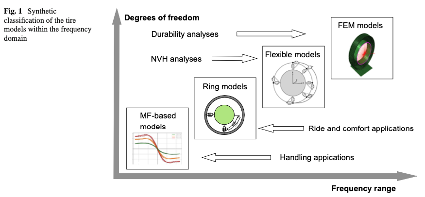
The continuously growing performance of modern computers is enabling the real-time target for increasingly complex of tire modeling for both offline and online real-time scenarios of use. In offline simulations, the focus is on achieving accurate results even with complex tire models. On the other hand, in real-time simulations, the model needs to repeatedly compute equations within a fixed time-step while receiving and providing inputs and outputs to external devices [3]. Figure 1 provides a synthetic classification of the tire modeling available in the current state of art, describing the respective frequency domain of applicability and the related fields of application.
The commonly adopted Lugre and Dugoff models offer a low computational cost solution suitable for real-time scenarios and even adoptable in embedded onboard applications within tire-based state estimators [4,5,6]. However, these models have the limitation of not considering the nonlinear variations of forces with slip coefficients [7]. This limitation is overcome by a more complex empirical formulation called Magic Formula [8], which is able to reproduce the transient slip behavior employing a relaxation length concept [9,10]. However, the accuracy of the Magic Formula decreases when thermodynamic and wear influences on tire grip and cornering stiffness can not be neglected, since this model only accounts for kinematic and dynamic variables. To properly consider these variables, the authors in [11, 12] developed a multiphysical tire modeling integrating the Magic Formula with additional polynomial dependencies on the tire thermodynamic and wear states.
It has to be pointed out that all the above-mentioned models are only applicable to a narrow frequency range since the transient relaxation length approximation is only sufficient for frequencies lower than 15 Hz [13]. Furthermore, a single-point contact configuration does not accurately represent the instantaneous contact patch extension. For this reason, although these models may represent a suitable trade-off between the necessary accuracy level and the computational cost, they are only suitable for vehicle handling simulation scenarios. For ride comfort applications, more complex tire models are required able to accurately describe the tire response in impact with small obstacles across a wider frequency range [14].
Literature offers a variety of tire models with differing degrees of complexity aiming to accurately simulate tire behavior in a wider frequency range. The MF-SWIFT model has been designed to extend the frequency range of the Magic Formula until 80–100 Hz, where the influence of the tire inertia properties on the dynamic behavior has to be considered. The formulation is based on a belt rigid-ring body modeling interposed between the wheel hub and the contact patch [15,16,17,18,19]. The tire-road interaction is still modeled by the standard Magic Formula approach, but the contact is extended by a cam-based model, enveloping the tire response to small unevenness [20,21,22,23].
Similarly to the standard Magic Formula, the SWIFT model does not take into account thermal and wear effects. Furthermore, the range of model application cannot exceed a certain frequency value above which the belt flexible modes become more predominant.
In [24], an in-plane flexible ring model was proposed in which the tread band was modeled as a deformable circular beam, with air-pressurized sidewalls represented by radially and tangentially distributed stiffnesses [24]. Later, models developed with multibody or FEA approaches enabled the representation of the tire dynamic behavior in a wider frequency range, allowing their employment in ride and comfort applications, as well as in NVH and durability analyses [25,26,27,28,29,30].
However, besides enabling the possibility to parameterize the models and to conduct sensitivity analyses without necessarily pre-acquired experimental data, an intrinsically higher number of degrees of freedom requires a bigger computational effort, which actually cannot be supported by embedded devices. This compromises their employment in onboard applications in the fields of virtual sensing and model-based control. The most adopted models include the commercial products as F-Tire, characterized by a flexible belt constituted by a finite number of masses connected with the rim [25,28], RMOD-K and CDtire, whose structures are described by detailed shell elements representing the belt and the sidewalls’ bodies [26, 27, 29].
The aim of this work is to propose an improved formulation of the rigid-ring-based on tire modeling, named SWIFT-evo formulation, suitable for ride-comfort simulations up to 80–100 Hz and able to account for the tire multiphysical effects, as temperature, wear and inflation pressure. The desired target consists of maintaining the model formulation with a minimum set of degrees of freedom to allow its employment in increasingly demanding real-time environments. The same is needed in terms of the number of model parameters to guarantee calibration feasibility even with a decreasing number of available experiments, further saving test-linked costs and time.
2 Rigid-ring dynamic model integrated with a multiphysical Magic Formula
The mathematical description of the belt body as rigid ring formulation was first proposed by the research group of the University of Delft. The developed formulation denominated SWIFT or SWIFT-TNO model allowed to enable the employment of the Magic Formula contact patch model on uneven road profiles including short wavelength obstacles [15,16,17,18,19]. Here, the tire belt mass is considered as a rigid ring coupled to the rim body through springs and dampers (linear and rotational). These elements represent the sidewalls’ mechanical properties, taking into account the variation of the pressurized air effect. A set of six second-order differential equations is employed to model the belt dynamics since both the in-plane and out-of-plane belt degrees of freedom are included in the model formulation.
Moreover, the rigid ring formulation includes a supplementary set of second-order differential equations to describe the dynamics of the contact patch. This is modeled as a two-dimensional body in contact with the effective plane and connected to the belt by means of residual springs and dampers. The road-tire interaction forces and moments at ground level are calculated using a Magic Formula model [9]: the forces acting on the effective plane are applied on the contact patch, while the forces acting out of the plane are considered to be directly applied on the belt.
To determine the effective plane where the tire kinematics and dynamics are evaluated, an enveloping cam model is applied allowing the conversion of the real road surface in an effective road profile for further single-point contact model [23].
Validation studies demonstrated that, in the frequency range in which the tire modes’ shape can be approximated to rigid ring motions, the SWIFT model is able to reproduce the tire behavior with a great level of accuracy [17, 19]. However, as well as the Magic Formula, the original SWIFT formulation considers only the kinematic and dynamic aspects of the tire’s mechanical response. Furthermore, several non-negligible linearization hypotheses are included to simplify the analytical description.
Several updates have been provided by the authors to enhance the accuracy and physical robustness of the originally proposed rigid ring formulation [8, 13, 17]. The work aims to incorporate further critical physical phenomena within the contact patch mechanics, to neglect the linearization concerning the kinematics definition and, finally, to consider the instantaneous contact patch variations due to tire-specific operating conditions.
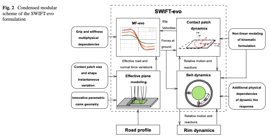
The enhanced SWIFT-evo formulation, schematized in Fig. 2, can be then employed as kinematic-dynamic infrastructure to include thermodynamic and wear influences on grip and tire braking and cornering stiffness. The proposed approach has been already performed and validated in [12], for characterizing the handling range of the tire behavior, corresponding up to 7–8 Hz [8] of the frequency range.
Coupling together the SWIFT-evo and MF-evo formulations, the authors aim to extend not only the dynamic frequency range of the original Magic Formula [9, 23], but also to take into account of the multiphysical dependencies extending the model applicability in the thermodynamic and wear domains. Furthermore, the natural frequency and damping ratio are made dependent on the vertical load, inflation pressure, and angular velocity through a semi-empirical relationship consistent with experimental modal analyses in available literature [31, 32].
This chapter comprehensively explains three independent subsystems of the updated SWIFT-evo model. The differences between the updated SWIFT-evo and the original SWIFT formulations are highlighted in each subpart, motivating the necessary changes. tire modeling
2.1 Belt dynamics
The frequency range of interest for the current work is such that the bending motions of the belt can be still hypothesized negligible so thus the tire can be modeled with a rigid ring (from 0 Hz until 80–100 Hz). In this frequency range, factors as the inertia forces and moments, the gyroscopic terms due to reference system rotations and the characteristics of sidewalls significantly affect the tire dynamic behavior [13, 33].
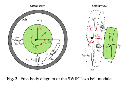
The addition of a rigid ring, mathematically representing the belt structure, allows describing with a satisfactory level of approximation the vibrating modes in which the tire dynamically behaves similarly to a rigid circular body. The mass and the inertia moments of the tire are divided between the belt and the rim in a defined percentage. The rigid ring is connected with the rim by means of translational and rotational springs and dampers that represent the tire sidewalls and the internal air influence (Fig. 3).
2.1.1 Mathematical description
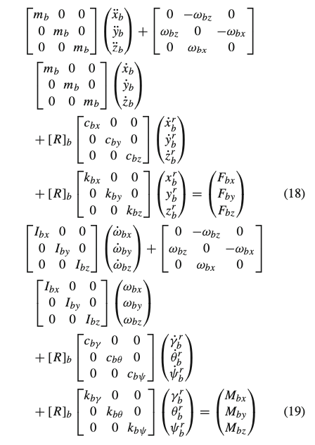
The dynamic belt Eqs. (1–6), characterizing the classical SWIFT formulation, are written in the belt-non-rotating ISO reference system (𝐵,𝑥𝑏,𝑦𝑏,𝑧𝑏), with the origin set in the belt center B. The 𝑦𝑏 axis is directed perpendicularly to the belt plane, while 𝑥𝑏 is horizontal [8]. The external forces and moments, appearing at the right member of Eqs. (1–6), are determined considering the forces generated at ground level due to the tire-road interaction the reactions of dampers and springs connecting the belt and the contact patch bodies.
On the left side of the equations, the inertia forces and moments as well as the gyroscopic terms, are expressed as function of the belt accelerations (𝑥¨𝑏,𝑦¨𝑏,𝑧¨𝑏,𝜔˙𝑏𝑥,𝜔˙𝑏𝑦,𝜔˙𝑏𝑧) and of the belt velocities (𝑥˙𝑏,𝑦˙𝑏,𝑧˙𝑏,𝜔𝑏𝑥,𝜔𝑏𝑦,𝜔𝑏𝑧). Dampers reactions (𝑐𝑏𝑥,𝑐𝑏𝑦,𝑐𝑏𝑧,𝑐𝑏𝛾,𝑐𝑏𝜃,𝑐𝑏𝜓) are calculated knowing the relative velocities (𝑥˙𝑏𝑟,𝑦˙𝑏𝑟,𝑧˙𝑏𝑟,𝛾˙𝑏𝑟,𝜃˙𝑏𝑟,𝜓˙𝑏𝑟) between the two bodies. From the knowledge of the relative displacements (𝑥𝑏𝑟,𝑦𝑏𝑟,𝑧𝑏𝑟,𝛾𝑏𝑟,𝜃𝑏𝑟,𝜓𝑏𝑟) the reactions of the springs can be calculated.
𝑚𝑏(𝑥¨𝑏−𝜔𝑏𝑧𝑦˙𝑏)+𝑐𝑏𝑥𝑥˙𝑏𝑟+𝑘𝑏𝑥𝑥𝑏𝑟+𝑐𝑏𝑧Ω𝑧𝑏𝑟=𝐹𝑏𝑥 (1)
𝑚𝑏(𝑦¨𝑏+𝜔𝑏𝑧𝑥˙𝑏)+𝑐𝑏𝑦𝑦˙𝑏𝑟+𝑘𝑏𝑦𝑦𝑏𝑟=𝐹𝑏𝑦 (2)
𝑚𝑏𝑧¨𝑏+𝑐𝑏𝑧𝑧˙𝑏𝑟+𝑘𝑏𝑧𝑧𝑏𝑟−𝑐𝑏𝑥Ω𝑥𝑏𝑟=𝐹𝑏𝑧 (3)
𝐼𝑏𝑥𝜔˙𝑏𝑥−𝐼𝑏𝑦Ω𝜔𝑏𝑧+𝑐𝑏𝛾𝛾˙𝑏𝑟+𝑘𝑏𝛾𝛾𝑏𝑟+𝑐𝑏𝜓Ω𝜓𝑏𝑟=𝑀𝑏𝑥 (4)
𝐼𝑏𝑦𝜔˙𝑏𝑦+𝑐𝑏𝜃𝜃˙𝑏𝑟+𝑘𝑏𝜃𝜃𝑏𝑟=𝑀𝑏𝑦 (5)
𝐼𝑏𝑧𝜔˙𝑏𝑧+𝐼𝑏𝑦Ω𝜔𝑏𝑥+𝑐𝑏𝜓𝜓˙𝑏𝑟+𝑘𝑏𝜓𝜓𝑏𝑟−𝑐𝑏𝛾Ω𝛾𝑏𝑟=𝑀𝑏𝑧 (6)
In Pacejka’s description [8], the relative velocities and angular velocities are defined as:
𝑥˙𝑏𝑟=𝑥˙𝑏−𝑉𝑥𝑏 (7)
𝑦˙𝑏𝑟=𝑦˙𝑏−𝑉𝑦𝑏 (8)
𝑧˙𝑏𝑟=𝑧˙𝑏−𝑉𝑧𝑏 (9)
𝛾˙𝑏𝑟=𝜔𝑏𝑥−𝜔𝑥𝑏=𝜔𝑏𝑥−𝛾˙ (10)
𝜃˙𝑏𝑟=𝜔𝑏𝑦−𝜔𝑦𝑏=𝜔𝑏𝑦−Ω+𝜓˙(𝛾+𝛾𝑏𝑟) (11)
𝜓˙𝑏𝑟=𝜔𝑏𝑧−𝜔𝑧𝑏=𝜔𝑏𝑧−𝜓˙ (12)
where the vectors (𝑥𝑏˙; 𝑦𝑏˙; 𝑧𝑏˙) and (𝜔𝑏𝑥; 𝜔𝑏𝑦; 𝜔𝑏𝑧) are the belt linear and angular velocities respectively, defined in the non-rotating belt reference system. Referring to the same reference system, the rim velocities are represented by the vectors (𝑉𝑥𝑏; 𝑉𝑦𝑏; 𝑉𝑧𝑏) and (𝜔𝑥𝑏; 𝜔𝑦𝑏; 𝜔𝑧𝑏). The latter vector is determined by transforming the axle angular velocities (𝛾˙; Ω˙; 𝜓˙) through a simplified linear transformation, as reported at the Eqs. (10 – 12).
It is worth noting that Eqs. (7–12) contain several approximations regarding the model kinematics. In particular, the rim velocities defined in the adopted reference frame are calculated starting from the axle velocities through linearization. This evaluation is valid in the hypothesis of low camber angles and neglecting eventual relative angles between the rim and the belt bodies. These approximations definitely lead to inaccuracies in more extreme tire operating conditions.
For this reason, the SWIFT-evo model has been conceived with a physically consistent formulation able to overcome kinematic approximations by adopting time-varying transformation matrices calculated instant by instant [34]. This ensures a more accurate model response and prevents accumulating errors, still employing the same ring-based scheme to model the tire structure:
[𝑅]𝑟=𝑓(𝛾,𝜓) (13)
[𝑅]𝑏=𝑓(𝛾𝑏𝑟,𝜓𝑏𝑟,𝛾˙𝑏𝑟,𝜃˙𝑏𝑟) (14)
where:
- [𝑅]𝑟 allows transposing the axle velocities into the rim reference system, (𝑂,𝑥𝑟𝑖𝑚,𝑦𝑟𝑖𝑚,𝑧𝑟𝑖𝑚), accounting rim instantaneous orientation and obtaining a not-approximated relationship;
- [𝑅]𝑏 rotates the vectors from the rim reference system to the belt non-rotating reference system, considering the time-varying belt-rim relative orientation that results from the differences between their angular velocities.
Therefore, in a simulation environment where the axle velocities (𝑥˙;𝑦˙;𝑧˙) and (𝛾˙;Ω;𝜓˙) are used as input of the tire model, the following relationship allows to define the model kinematics without omitting any physical terms:
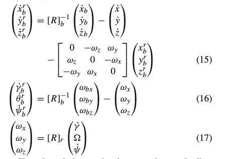
Here the relative motion between the two bodies, as well as the associated elastic and damping reactions, have been defined in the rim reference system. Therefore, the reactions have to be further rotated into the belt non-rotating reference system where the equilibrium equations are then evaluated (18). It is worth highlighting that the revised formulation now also includes within the lateral dynamics the gyroscopic terms neglected in the previously reported equations [13, 17]:
2.1.2 Additional physical dependencies of the belt parameters
To guarantee an enhanced consistency of the rigid ring-based model with physical experimental evidences regarding the modal analysis available in literature, further parameter dependencies have been included. These formulations have been specifically conceived to enable a robust calibration process employing a minimum number of additional parameters compared to the pre-existing rigid-ring implementation.
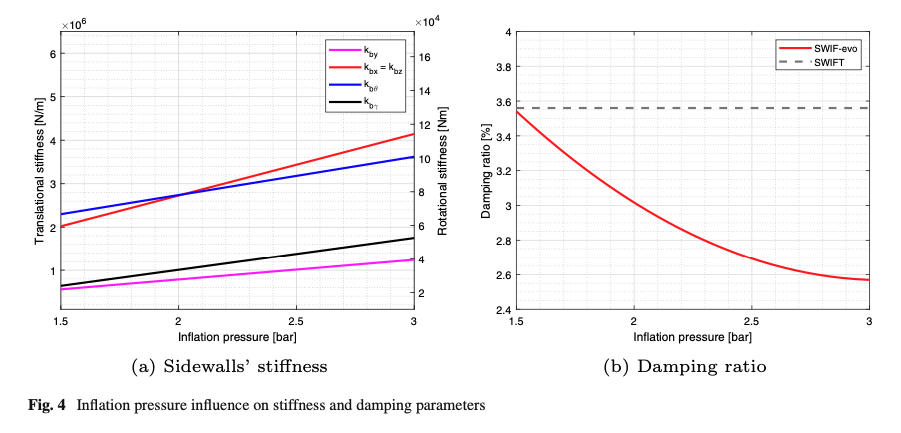
A linear relationship between the sidewalls’ stiffness and the inflation pressure has been inherited in this work (Fig. 4a): this formulation assures the desired increasing trend of the natural frequency with the tire internal pressure with a satisfying degree of accuracy [35, 36].
According to the experimental campaigns in [31, 32, 37], a polynomial equation is implemented to describe the physical trend of a decreasing damping ratio with the inflation pressure in radial direction (𝑐𝑏𝑥=𝑐𝑏𝑧) (Fig. 4b). Since the damping ratio optimization can be easily separately per each value of inflation pressure, the robust fitting of this second-order polynomial dependency can be subsequently calibrated starting a dataset with three different pressure levels.
The empirical formulation introduced by Zegelaar [13] has been inherited from the original SWIFT model. This formulation considers a square-root relation between the sidewalls’ stiffness and the angular velocity. The parameters 𝑞𝑉𝑏𝑥 and 𝑞𝑉𝑏𝑧 are used to control the velocity influence on the longitudinal and vertical tire natural frequency respectively [8]. The variable 𝑄𝑉 governing the dependency in Eq. (22) represents the sidewalls deformation velocity due to the tire rotation speed and to the relative displacement between the rim and the belt. The mentioned formulation guarantees a decreasing trend of the tire in-plane natural frequencies with the rotational speed, coherently with the literature experimental works performed to analyze rotating-tire modal properties [38,39,40,41].
However, the main limitation of the original formulation consists in the fact that it does not consider the necessary load dependency. Many studies [31, 42] demonstrated that the radial natural frequency increases with higher values of the load applied due to a nonlinear increase of the radial sidewalls’ stiffness. An empirical tangent hyperbolic equation has been chosen to describe this phenomenon, since this formulation ensures stability and allows to model the dependency with a minimum number of parameters. Furthermore, this formulation assures a saturation load level of the increasing natural frequency, in according with experimental evidences [42]. The maximum percentage variation in all the load range can be easily controlled by means of the parameter 𝑞𝑏𝐹𝑛𝑧1, while the parameter 𝑞𝑏𝐹𝑛𝑧2 is used to impose the vertical load value saturating the dependency.
The resulting formulation governing the radial sidewalls’ stiffness trend with inflation pressure, angular velocity, normal load and sidewalls’ deformation, is proposed at Eqs. (20–26). In particular, the dependencies have been expressed defining the variations with respect to the nominal conditions (𝑘𝑏𝑥0=𝑘𝑏𝑧0,𝑓𝑥0=𝑓𝑧0), identified by radial natural frequency and stiffness of the non-rotating and unloaded tire at the nominal inflation pressure:
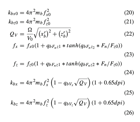
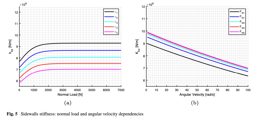
Figure 5 provides a graphical representation of the radial sidewalls’ stiffness dependencies, reporting their trend for different values of normal load and angular velocities (subscript 1 indicates the minimum level while subscript 5 indicates maximum one), and for a constant inflation pressure. tire modeling
2.2 Contact patch mechanics
The second member of the differential Eq. (18) refers to forces and moments which excite belt dynamics and related to the tire-road interaction. The contact-state is modeled through analytical formulations taking into account the definition of the effective plane, the contact patch normal and the contact patch kinematics.
The reference system (C, 𝑥𝑐, 𝑦𝑐, 𝑧𝑐) of the contact patch, has been chosen in accordance with [8]. The origin is the contact point C and 𝑧𝑐 axis corresponds to normal 𝑛→ of the effective road plane, evaluated by a specifically modified envelope model. The 𝑥𝑐 axis is the intersection between the rim plane and the road surface, so that the 𝑦𝑐 axis is to compose a left-handed triad.
It is worth highlighting that here the contact forces and moments are evaluated within the contact patch reference system. Therefore, they have to be rotated into the belt non-rotating reference system in order to be used in Eq. (18). Thus, the rotation matrix [𝑅]𝑐𝑝𝑏 has been defined to rotate vectors from the reference system (C, 𝑥𝑐, 𝑦𝑐, 𝑧𝑐) to the reference system (B, 𝑥𝑏, 𝑦𝑏, 𝑧𝑏):
[𝑅]𝑐𝑝𝑏=[𝑅]𝑏−1[𝑅]𝑐𝑝 (27)
This equation has been determined starting from the matrix [𝑅]𝑏 defined in Eq. (14) and the matrix [𝑅]𝑐𝑝 indicating the orientation of the contact patch reference system with respect to the rim reference system (𝑂,𝑥𝑟𝑖𝑚,𝑦𝑟𝑖𝑚,𝑧𝑟𝑖𝑚). The latter matrix has been defined depending on the contact patch unit vectors evaluated within the rim reference system (𝑥𝑐→,𝑦𝑐→,𝑛→) coherently with the previously mentioned hypothesis:

Once determined [𝑅]𝑐𝑝𝑏, it can be employed to rotate forces 𝐹𝑐𝑥, 𝐹𝑐𝑦 and torques 𝑀𝑐𝑥, 𝑀𝑐𝑦, 𝑀𝑐𝑧 exciting the belt dynamics upon the effective road plane. Also the transfer couples due to the loaded radius are taken into account, in according with [8]:
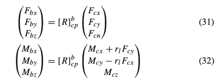
The normal force 𝐹𝑐𝑛 is considered to be applied directly on the rigid ring, so that it can be calculated with an empirical nonlinear relationship with the tire deflection. The latter is function of the instantaneous loaded radius, evaluated depending on the wheel center position and on the effective plane location and orientation. The adopted normal force calculation also considers the inflation pressure, camber angle, rotational speed velocity effects on tire stiffness and radii variations [13].
The forces (𝐹𝑐𝑥, 𝐹𝑐𝑦) and torques (𝑀𝑐𝑥, 𝑀𝑐𝑦, 𝑀𝑐𝑧), linked to the tangential interaction are determined coherently with [8, 11], starting from kinematic slips both in steady-state and transient conditions.
2.2.1 Effective plane and contact patch normal
The point C and the normal 𝑛→ define the position and the orientation of the instantaneous effective road plane that is determined through an empirical enveloping model. The original methodology, developed by Schmeitz [17, 18], to reproduce the tire response on arbitrary uneven profile, relies on the effective road profile evaluation. This approach has been enriched by the authors introducing the variations of the real contact patch in terms of extension, shape and position as well as of the cams’ geometrical characteristics.
In particular, the technique is based on the assumption that, in quasi-static conditions, the behavior of the real tire on the actual road surface is well approximated by the single contact model response on the effective road plane [13, 20].
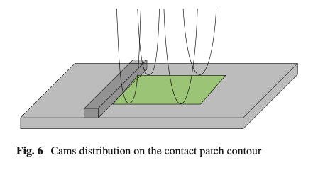
The SWIFT model’s approach employs elliptical cams placed on the contact patch contour to generate the effective surface on three-dimensional road unevenness. The cams’ dimensions are kept constant and the effect of the vertical load and inflation pressure are included only within the variation of the contact patch dimensions through an empirical formulation [8, 17].
However, the elliptical cams do not allow to reproduce the typical initial tire-obstacle indentation phase, in which the tire does not immediately react to the obstacle presence in the vertical direction. This phenomenon is evident both from the experimental campaigns available in the literature [13, 17, 22] and from the results in Fig. 12. For this reason, the front cams have been geometrically substituted by the authors with hermitian parametric curves and keeping the rear cams elliptical for the lift obstacle (front elliptical and rear hermitian for the descent obstacle), so obtaining a four-cams’ layout placed on the contact patch contour (Fig. 6). Furthermore, the contact patch instantaneously varies its size, shape and position with the operating conditions in according to the nonlinear dependency derived from experimental data and/or modeled with a higher order tire structural model [27,28,29,30].
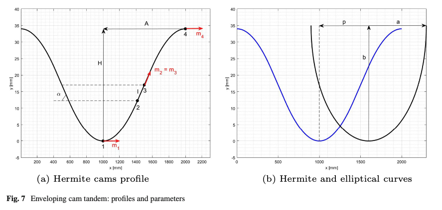
The hermitian cam profile, presented in Fig. 7a is mathematically defined through four points. The points 1 and 2 and the points 3 and 4 are connected through spline curves, respectively, while a linear segment connects the points 2 and 3. This geometry assures that the shape of the ascent part of the wheel vertical displacement (and therefore of the contact patch in quasi-static conditions) has an horizontal tangent at the initial point touching the obstacle. This means that, besides the cams’ location within the contact patch contour, the vertical height of the hermitian cams is constrained to be equal to the obstacle height H and the spatial derivatives located at points 1 and 4 are horizontal. The only independent variables are the cam’s half width A, the extension of the central linear segment l and the angle 𝛼. The four characteristic points can be therefore described as follows:
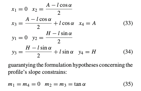
The typical cams’ tandem is illustrated in Fig. 7b, where the rear cam is modeled with an elliptical profile and characterized by the semi-axes’ dimensions a and b, and the quantity p, depending on the contact patch contour, represents the distance between front and rear cams.
The procedure applied to define the effective road plane position and orientation is inherited from the work of Schmeitz [17, 21, 23]: the vertical position of the plane height is calculated by taking the average of the z-coordinates across the width for front and rear cams; the longitudinal slope is determined from the average angle across the contact patch width for both front and rear cams, while the transverse slope is calculated from the average angle across the contact length for both left and right cams.
It is worth highlighting that, when the contact patch assumes symmetric configuration (i.e., when the camber angle is close to zero), the cams’ shapes and horizontal distances are supposed to be equal both at left and right side of the contact patch. With the presence of a significant wheel orientation resulting in particularly asymmetric contact patch, the wheel alignment could modify not only the contact patch contour but also the enveloping behavior (i.e., the cams’ dimensions). However, this is not a topic of the current work, focusing the model’s validation only on the tire in-plane response.
For the sake of completeness, the model validation has been carried out on single obstacles, defining the obstacle height H with respect to the initial road effective plane. In case of more complex road profiles, the surface is modeled as a series of discrete obstacles, whose height is defined with respect to the instantaneous effective road plane established at the moment of the first impact. tire modeling
2.2.2 Contact patch dynamics and kinematics
The modeling of transient slip dynamics does not differ from pre-existing formulations based on the relaxation length concept and on the contact patch in-plane dynamics. The in-plane forces and related torques are determined via an extension of the adopted steady-state slip model, including transient brush-model dynamics. The employed set of first-order differential Eqs. (36–37) receives in input the slip velocities of the contact patch and provides in output the transient slip quantities (𝜅′,𝛼′) which in their turn are employed as inputs of the MF-based slip model [8, 11]:

According to [8], it is worth highlighting that the integration of the transient slip dynamics within the rigid ring model leads the relaxation lengths to become function of the longitudinal and lateral tire’s overall stiffnesses. Indeed, residual springs are specifically added to connect the belt and the contact patch bodies, considering the latter as a three-degree of freedom small mass only moving within the road effective plane. A graphical representation of the contact patch mechanics is provided by Fig. 8.
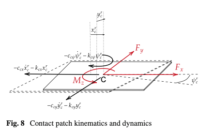
The contact patch dynamics modeling requires another set of 3 s-order differential Eqs. (38–40) to determine the time-varying contact patch slip velocities within the road plane. These equations include residual springs and dampers’ reactions, inertia and contact slip forces and torques acting within the effective road plane:

The reactions of the residual springs 𝑘𝑐𝑥𝑥𝑐𝑟, 𝑘𝑐𝑦𝑦𝑐𝑟, 𝑘𝑐𝜓𝜓𝑐𝑟 and dampers 𝑐𝑐𝑥𝑥˙𝑐𝑟, 𝑐𝑐𝑦𝑦˙𝑐𝑟, 𝑐𝑐𝜓𝜓˙𝑐𝑟 correspond to the forces exciting the belt dynamics on the effective road plane, 𝐹𝑐𝑥,𝐹𝑐𝑦,𝑀𝑐𝑧 reported at Eq. (32). They are determined proportionally to the relative kinematics between the belt and the contact patch bodies at the ground level, which in turn are derived from the instantaneously calculated contact patch slip velocities and belt velocities at ground level, in accordance with [8].
The longitudinal and lateral forces 𝐹𝑠𝑥,𝐹𝑠𝑦 and the yaw moment 𝑀𝑠𝑧 appearing at second member of Eqs. (38–40) are evaluated via the MF-evo model [11, 12], in according with the Pacejka hypothesis [8], which also takes into account static contact patch deflection. On the other hand, the derived torques 𝑀𝑠𝑥,𝑀𝑠𝑦, acting out of the effective road plane, are considered to be directly applied on the belt: therefore they coincide with the moments 𝑀𝑐𝑥,𝑀𝑐𝑦 reported at Eq. (32).
2.2.3 MF-evo
In the classical SWIFT model formulation, the forces acting on the contact patch are calculated using an underlying Magic Formula (MF) which also takes into account the relaxation length behavior of the tire. However, it is worth noting that this formula overlooks several multiphysical phenomena that can heavily influence the tire’s performance in various operating contexts, such as thermodynamic and wear phenomena.
This is particularly relevant in motorsport, but it could be also significant in the control design of the critical maneuvers and safety-linked scenarios. In fact, in these applications, the ability to correctly evaluate the potential grip or the actual stiffness levels could provide a significant advantage [6, 12, 14].
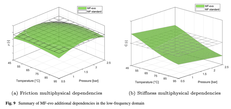
The level of grip is dependent on compound temperature gradient and inflation pressure level, while wear leads to grip degradation. Braking and cornering stiffness decrease with higher temperature and vary with internal air pressure and wear. The MF-evo includes these phenomena considering additional parameters (𝑥𝑒𝑣𝑜) that define the multiphysical dependencies of micro- and macro- coefficients (𝑥𝑠𝑡𝑑) of the standard Magic Formula (MF). The inherited formulation has been summarized in Eq. (41) and not included in this work since it has been specifically addressed by the authors in the previous works [11, 12]:

where the employed dependencies affect the nominal value of the grip coefficient and the maximum value of the stiffness (𝑝𝐷𝑥1,𝑝𝐷𝑦1 and 𝑝𝐾𝑥1,𝑝𝐾𝑦1) and their variations with vertical load (𝑝𝐷𝑥2,𝑝𝐷𝑦2 and 𝑝𝐾𝑥2,𝑝𝐾𝑦2) both in lateral and longitudinal directions, as illustrated in Fig. 9.
3 Calibration procedure and results
The current chapter describes the experimental campaign and the corresponding calibration procedure carried out with the aim to characterize the real tire adopting only non-destructive and non-invasive testing techniques. The calibration workflow is described in Fig. 10. The aim is to perform separate measurements and processing sub-phases in order to isolate the tire’s physical properties and, consequently, to identify specific model parameters with the corresponding dependencies.
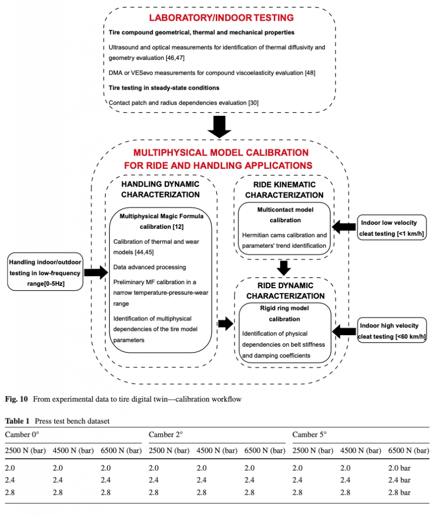
Once illustrated the experimental activities carried out in both kinematic and dynamic scenarios, the calibrated responses of the SWIFT-evo and the SWIFT [15,16,17,18,19] models are compared toward the collected data. It is worth mentioning that the authors aimed to guarantee objectivity and to minimize the potential impact of the gradient-based optimization techniques within the models’ calibration process. For this purpose, it has been assured that the parameters’ starting sets of different formulations ensured analogous trends toward the same variables of interest [43].
Finally, a sensitivity analysis is proposed to analyze the impact of the inserted load and pressure physical dependencies compared to the pre-existing formulations. tire modeling
3.1 Experimental campaign
The calibration results of the MF-evo have been inherited from a previous research work [12], employing handling data acquired on track. Pre-calibrated tire thermal and wear models [44, 45] have been employed to obtain further physical channels per each dataset: temperature gradient, inflation pressure and wear variations. The parameterization of these models has been performed employing a non-destructive experimental methodology, including optical and ultrasound measurements to identify tire’s thermal diffusivity and geometrical quantities [46, 47]. The viscoelastic characterization of the compound has been performed by means of an innovative instrumentation [48] as an alternative to the traditional destructive methodologies [49].
Additional parametrization regarded the contact patch modeling (in terms of size and shape), which has been carried out per different levels of inflation pressure, camber angle and vertical load on a dedicated test bench [30], making use of force–deflection and footprint sensors. Regarding the tire’s radii parameterization, an experimental campaign has been carried out including force–deflection measurements and footprint acquisitions in static conditions. The data collection has been then extended employing a pre-calibrated multi-body tire model to include centrifugal effects too [30]. The influence of the camber angle on the tire behavior has been hypothesized symmetrical so that only negative camber values have been included within the static experimental doe.
Since the tire’s response to small obstacles is strongly influenced by stiffness and contact patch dimensions [13, 20], the previously collected contact patch data to calibrate thermal and wear models, have been also employed for the characterization of the tire’s enveloping behavior.
Indeed, to calibrate the enveloping tire behavior, both the contact patch and radii data and the data collected through a quasi-static testing methodology, proposed in [50], have been employed. In particular, to reproduce the motion of a tire rolling over an obstacle, the rim’s supporting system was constrained to allow only the rotation around the ISO-y axis and the linear movement along the ISO-z axis. The test has been repeated inflating the tire with three different pressures and applying three different static loads, selected to cover the entire tire operating domain. To this purpose, the tests have been conducted in a low-velocity range (quasi-static conditions (<1km/h [13])) to decouple the experimental response from the possible dynamic effects.
The tire dynamic behavior has been investigated through high-velocity cleat tests, which have been carried out with the standard routine, reported in [51]. It consists of a steel drum with a rectangular cleat counter-rotating to the tire mounted on a fixed hub. Forces and torques, measured at the wheel center, are then employed to calibrate belt stiffness and damping coefficients, with contact patch enveloping and MF-evo fixed. To identify the supposed physical dependencies, the test plan included three different inflation pressures, three static vertical loads and two angular velocities.

3.2 Parameters’ starting set and cost function
Due to the intrinsic empirical formulation and the amount of parameter dependencies to be accounted for, the accuracy and the robustness of the model’s output are directly linked to the degree of completeness and quality of the acquired data.
Both the standard MF and the multiphysical MF-evo models have been identified and validated with the methodology described in [12], employing handling data covering a wide range of thermodynamic and wear conditions. The results are available in [12] and will be not included in the following study. It is worth highlighting that the influence of the multiphysical effects on the contact mechanics quantities (grip and stiffness) has been neglected in the validation phase since the experimental campaign was conducted in a narrow thermodynamic and wear range (standard test rig boundary conditions [51]).
The kinematic calibration of the effective plane and of the contact patch normal relies on the characterization of the enveloping model parameters (defining the geometry of hermitian and/or elliptical cams and their variations toward further variables). Therefore, a specific cost function, based on the experimental data reproducing the wheel vertical displacement Z toward the longitudinal advancing X in quasi-static conditions, has been employed as reported in (42):

The starting set of parameters was chosen for different models to ensure a similar simulation output.
The parameters governing the dynamic tire response have been identified through a time-domain approach, minimizing the error function between the simulated vertical 𝐹𝑧 and longitudinal 𝐹𝑥 forces and the respective acquired measurements, as reported in (43):

Preliminarily, the models have been calibrated via a numerical procedure with the load influence supposed fixed to zero to evaluate the lower and upper boundary of the tire dynamic frequency range. Then, boundary conditions have been imposed on the parameters governing the load dependency employing the entire dataset acquired in different load and velocity ranges. Since the inflation pressure does not significantly vary during the cleat test, the described optimization process has been separately performed for different constant pressures and the related influences have been subsequently calibrated. The starting set of parameters was chosen for different models to ensure a similar simulation output.
3.3 Kinematic quasi-static validation
A quasi-static validation has been performed to demonstrate the enhanced response of the enveloping model with front hermitian cams toward the previously adopted elliptical cam tandem. This is because the effective road profile is assumed to be unaffected by transient tire dynamics in low-velocity conditions.
The parameters’ identification has been repeated per each experimental condition and the values of the optimized parameters have been collected and reported, for the sake of completeness, in Table 3 and Table 4. In this phase, since the robustness of a model is strongly related to the calibration process repeatability, the associated risks of over-fitting should be avoided, especially with empirical formulation. Therefore, it’s important to ensure that the identified quantities autonomously create monotone observable trends toward the variables of interest [12].
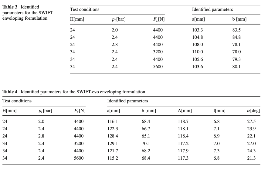
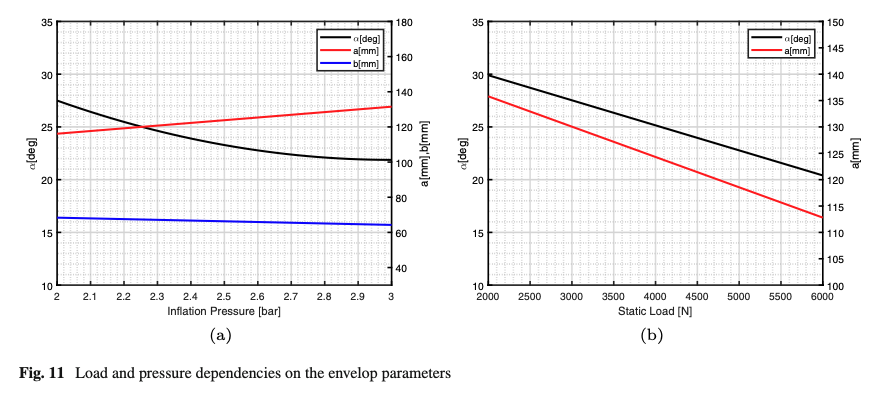
It can be easily observed that, although the implementation of the hermitian curves requires the identification of a higher number of parameters, Eq.s 33, 34, 35), the increasing parametrization complexity does not compromise the robustness of the process. Indeed, the Table 4 shows the typical monotone variation of the identified parameter 𝛼 in the explored discrete domain, allowing to easily extend the 𝛼 parameter’s continuity via polynomial functions, as presented in Fig. 11. As expected, the parameters A and l do not vary significantly and are assumed constant, being more correlated with the tire’s geometrical properties.
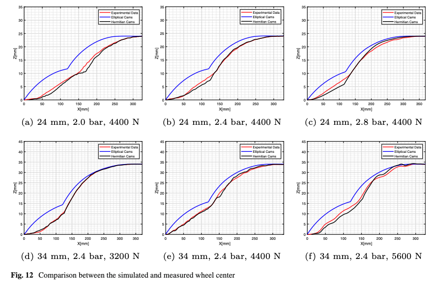

The kinematic response of the SWIFT’s and the SWIFT-evo’s enveloping model are compared in the Euclidean domain in Fig. 12, in which the accuracy of both the models has been quantified through the root mean square error toward the experimental measurements in Table 5. The reported results demonstrate the ability of the proposed enveloping model to correctly reproduce both the initial and the final phases of the wheel center path during the tire-obstacle impact.
3.4 Dynamic validation
Both SWIFT and SWIFT-evo models have been parameterized with the same calibration procedure toward the measurements acquired during the high-velocity cleat experimental campaign reported in Table 2 and described in [51].
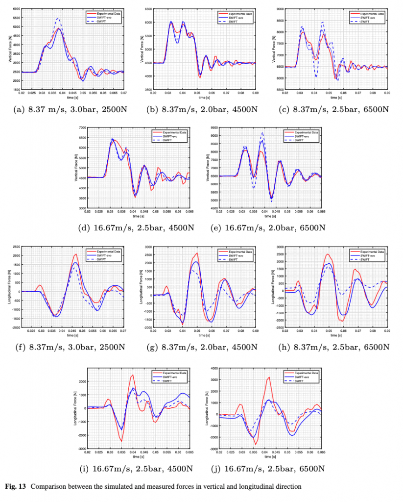
Vertical and longitudinal forces, outputs of the SWIFT and SWIFT-evo models, are compared with the respective measurements in Fig. 13, while the root mean square errors [52] per each experimental condition are compared in Table 6 and Table 7, respectively.
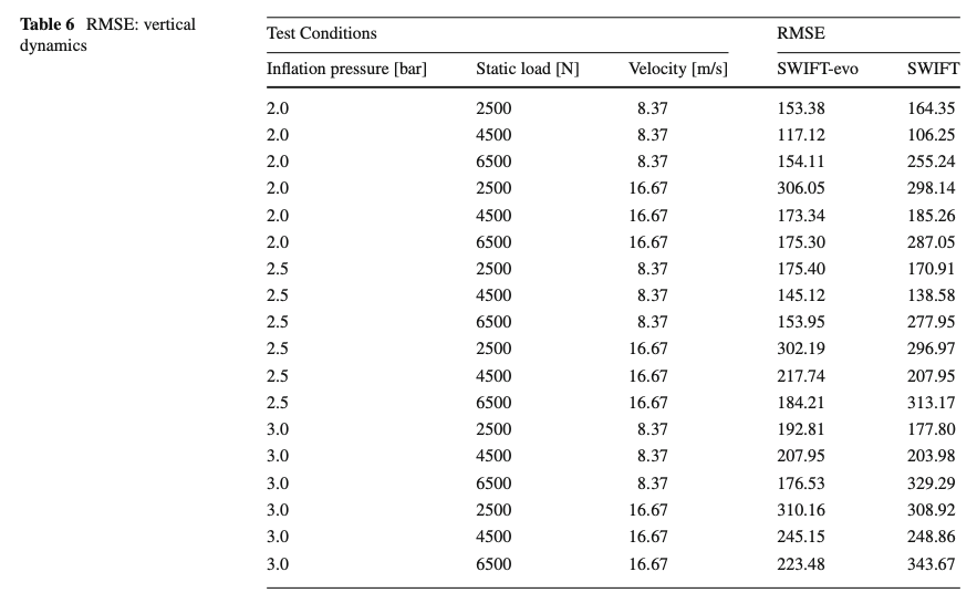
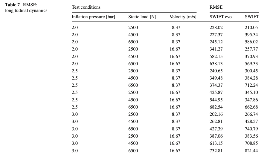
Vertical and longitudinal forces, outputs of the SWIFT and SWIFT-evo models, are compared with the respective measurements in Fig. 13, while the root mean square errors [52] per each experimental condition are compared in Table 6 and Table 7, respectively.
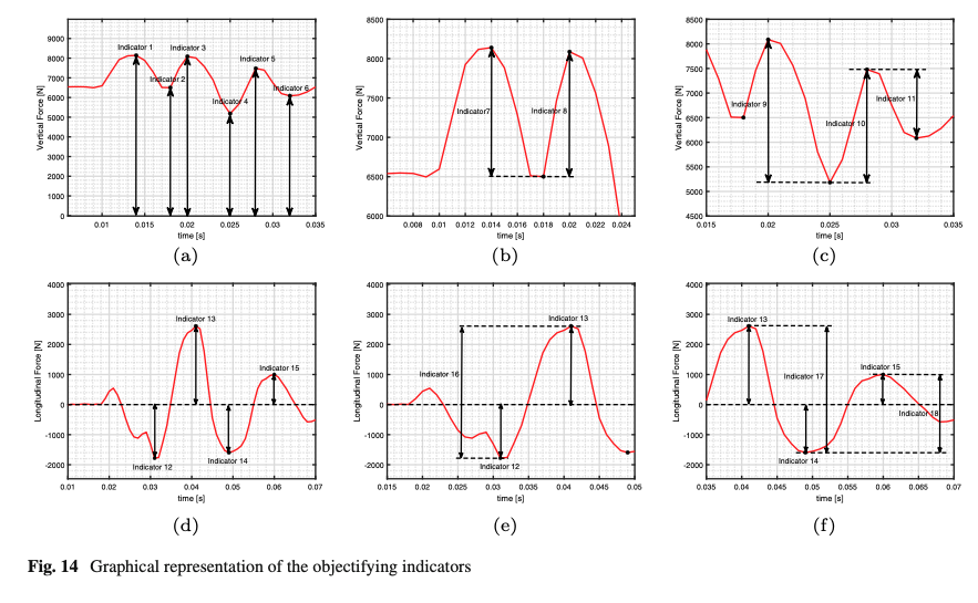
Furthermore, to objective the results, several indicators have been defined in both the impulsive tire-cleat impact and subsequent tire-free-oscillations phases. Regarding the vertical dynamics, the indicators 1–11 are illustrated in Fig. 14a–c. The indicators 7 and 8 are mainly related to the tire envelope behavior since they define the response during the passage on the obstacle. Instead, the Indicators 9, 10 and 11 are influenced by the tire modal properties, affecting the vibration motion after the cleat passage. The indicators describing the longitudinal dynamics are illustrated in Fig. 14d–f.
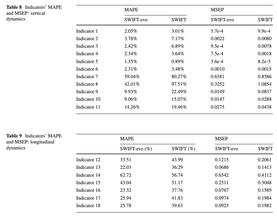
The mean absolute (MAPE [53]) and the mean square (MSEP [54]) percentage errors for all the above indicators have been evaluated on the entire dataset in Table 8 and Table 9, demonstrating the improved accuracy of the SWIFT-evo model, in both phases: during the contact with the cleat and during the subsequent free-oscillations.
3.5 Sensitivity analysis
A sensitivity analysis has been included with the aim of understanding the impact of the additionally introduced relationships on the global model’s response.
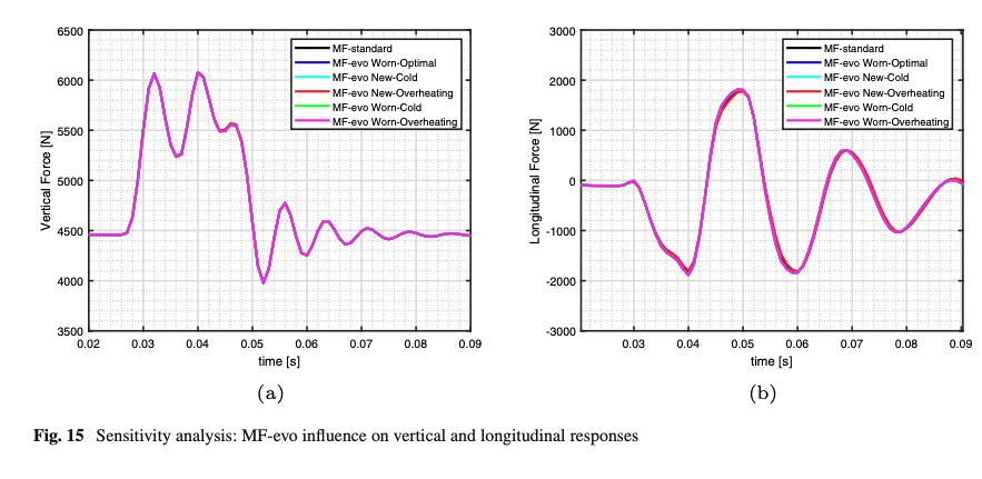
Previous works demonstrated that the MF-evo multiphysical dependencies were crucial to extending the MF model in the low-frequency handling domain within a wider range of thermodynamic and wear conditions [11, 12]. For the sake of completeness, the impact of the calibrated MF-evo model has been investigated in an impulsive tire-obstacle scenario. As illustrated in Fig. 15, the contact patch mechanics parameters do not significantly affect global tire behavior.
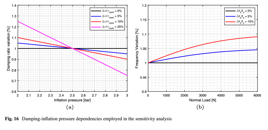
The supposed decreasing trend between the damping ratio and the inflation pressure, investigated in the literature [31, 32, 37], has been confirmed within the calibration process. A dedicated sensitivity analysis has been carried out comparing the model response for different ranges of the linear pressure-damping dependency (Fig. 16a), supposing constant static load and tire angular velocity quantities. Starting from the damping ratio identified at nominal inflation pressure 2.5 bar, three differing variation levels have been investigated in terms of vertical and longitudinal responses. The percentage deviations of each indicator with respect to the simulation performed in the nominal pressure conditions have been compared at the Tables 10 and 11
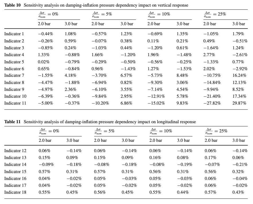
Since the indicators show a clear trend with the employed damping variation, the inserted dependency provides another useful degree of freedom for the model parametrization. This allows to optimize the model response based on the indicators’ variation with the inflation pressure variable, without additionally increasing the calibration complexity.
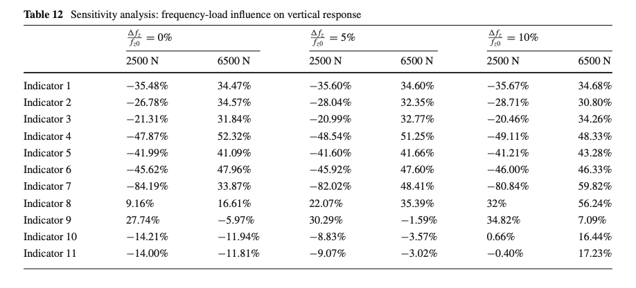
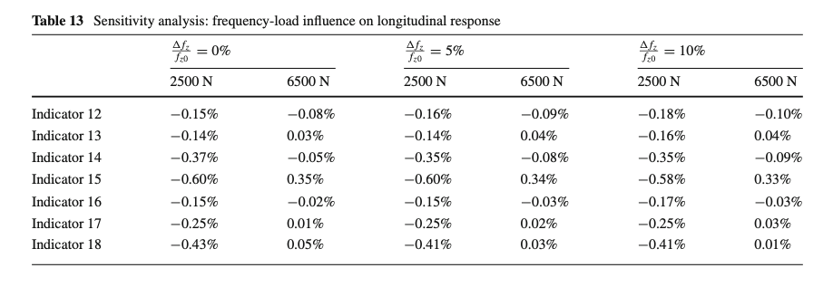
A further analysis has been conducted to investigate the effect of the parameters affecting the tire radial natural frequency, reporting percentage variations with respect to the unloaded tire condition(Fig. 16b). The indicators have been evaluated exploring separately three load ranges (already included in the experimental campaign) keeping constant inflation pressure and angular velocity. The percentage deviations with respect to the nominal load condition have been then compared per each employed load dependency (Tables 12, 13). It’s important to point out that the employed percentage variations are not so significant to considerably affect the distance between peaks and valleys within the time domain, especially if the simulations are performed with a sample frequency of 1000 Hz. Also in this case, the indicators show a clear trend allowing to quantify the monotone load dependency with the aim of extending the model accuracy.
3.6 Models’ comparison in extreme kinematic conditions
The accuracy of the simulation results can be significantly affected by the linearizations adopted in the original SWIFT formulation. As it has been explained at the chapter 2, the SWIFT-evo equations modeling the tire kinematics have been derived through a rotation matrix approach with the aim of minimizing any modeling approximations.
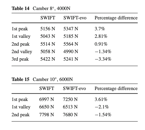
In order to evaluate the impact of this improvement, the vertical tire responses have been analyzed assuming high camber angle values. The model response achieved by employing the nonlinear SWIFT equations chosen by the authors have been compared with that obtained through a linearized SWIFT formulation in Fig. 17.
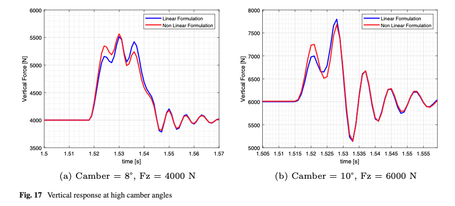
In Tables 14 and 15, the differences between the peak and valleys are objectively quantified for the two examined conditions.
4 Tire Modeling: Conclusion and future developments
An improved formulation of a rigid-ring approach, originally developed within the SWIFT model, is proposed by the authors with the aim of increasing the model reliability and extending its applicability domain.
The SWIFT-evo model has been conceived with a physically consistent formulation that eliminates kinematic approximations and linearization hypotheses by adopting time-varying transformation matrices calculated instant by instant, not neglecting eventual relative angles between rim and belt bodies and within dynamic applications characterized by a higher camber angle.
Several non-negligible linearization hypotheses and kinematic approximations are included into the original SWIFT model to simplify the analytical description. These have been overcome by the authors to allow the exploitation of the SWIFT-evo formulation in more extreme kinematic conditions, for example with higher camber angles. On one hand, the removal of these simplifications allows the employment of the same ring-based formulation, whose parameterization is based on well-know and industry standard testing routines. On the other hand, a more accurate mathematical description prevents accumulating errors.
The contact mechanics of the SWIFT approach, employing elliptical cams placed on the contact patch contour to generate the effective surface on three-dimensional road unevenness, has been updated. The front cams have been substituted with hermitian parametric curves, allowing to reproduce the typical initial tire-obstacle indentation phase, and the cams’ dimensions are not more kept constant. Furthermore, the contact patch size, shape and position now vary with the operating conditions in according to the nonlinear dependency derived from experimental data and/or modeled with a higher order tire structural model.
Finally, the natural frequency and damping ratio are made dependent on the vertical load, inflation pressure, and angular velocity through a semi-empirical relationship consistent with experimental modal analyses in available literature. The MF-standard has been substituted by an advanced multiphysical MF-evo in order to improve the model performance in handling applications including a significant influence of thermodynamic and wear effects.
To assess the model’s accuracy, both the original SWIFT and the proposed enhanced SWIFT-evo formulations have been calibrated and compared toward the same experimental data. For the sake of completeness, the calibration procedure has been described, putting in evidence the specific datasets used to parameterize singular sub-models and physical dependencies. SWIFT-evo model’s sensitivity analysis is also provided to investigate the impact of the proposed improvements on the overall tire response.
The aim the SWIFT-evo model is to provide a reliable and computationally cost-effective formulation for both handling and ride and comfort scenarios. In addition, another desired objective is to allow the model employment in embedded onboard applications in the fields of virtual sensing and vehicle model-based control.
Although the MF-evo integration represents the first step for giving a multiphysical identity to the model, it does not significantly affect the vertical response in ride and comfort scenario. Therefore, an interesting topic of a future work will address the investigation of the thermal and wear effects upon the tire modal response.
Another research step will consist in the study of the enveloping cam-tandem sub-model calibration toward the inclination angle variable, extending the asymmetric contact patch validation. In the current work, both the horizontal distances between left and right cams have been supposed to vary with the inclination angle proportionally to the respective contact patch size, in according with the contact patch data.
Finally, the application in a dedicated vehicle simulation environment, allowing to couple the vehicle’, suspension’s and tire’s dynamics, will be addressed. The development of this application, including high-precision kinematic relationships and tire’s multiphysical nonlinear dependencies, could represent a holistic solution for optimizing the vehicle performance in both handling and ride comfort scenarios.
Data Availability
The datasets generated and analyzed during the current study are not publicly available but are available from the corresponding author on reasonable request.
Funding
Open access funding provided by Università degli Studi di Napoli Federico II within the CRUI-CARE Agreement.
Author information
Authors and Affiliations
- Department of Industrial Engineering, University of Naples Federico II, Via Claudio 21, 80125, Naples, ItalyMario Barbaro, Andrea Genovese, Francesco Timpone & Aleksandr Sakhnevych
Corresponding author
Ethics declarations
Conflict of interest
The authors have no relevant financial or non-financial interests to disclose.
Additional information
Publisher’s Note
Springer Nature remains neutral with regard to jurisdictional claims in published maps and institutional affiliations.
Rights and permissions
Open Access This article is licensed under a Creative Commons Attribution 4.0 International License, which permits use, sharing, adaptation, distribution and reproduction in any medium or format, as long as you give appropriate credit to the original author(s) and the source, provide a link to the Creative Commons licence, and indicate if changes were made. The images or other third party material in this article are included in the article’s Creative Commons licence, unless indicated otherwise in a credit line to the material. If material is not included in the article’s Creative Commons licence and your intended use is not permitted by statutory regulation or exceeds the permitted use, you will need to obtain permission directly from the copyright holder. To view a copy of this licence, visit http://creativecommons.org/licenses/by/4.0/.